5C-HFBT Coaxial Cable
This specification covers the 5C-HFBT Coaxial Cable for connection of devices intended for television reception like a satellite broadcasting of 75 ohms characteristic impedance or related devices.
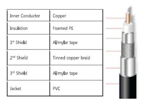
CONSTRUCTION OF THE 5C-HFBT Coaxial Cable
| ITEM | UNIT | 5C-HFBT | 5C-HFBT-A | ||
| Inner conductor | Material | — | Copper | ccs | |
| Diameter | mm | 1.20 ± 0.03 | 1.02 ± 0.05 | ||
| Insulation | Material | — | Foamed PE | Foamed PE | |
| Thickness | mm | 1.90 ± 0.05 | 1.73 ± 0.05 | ||
| Diameter | mm | 5.00 ± 0.1 | 4.57 ± 0.1 | ||
| Color | — | Natural | Natural | ||
| Outer conductor | lst shield | Material | — | Al/mylar tape | Al/mylar tape |
| Thickness | mm | 0.042 ± 0.003 | 0.051 ± 0.003 | ||
| 2nd shield | Material | — | Tin-coated Annealed Copper (TA) | Aluminum wire (A) | |
| Individual wire diameter | mm | 0.120 ± 0.005 | 0.150 ± 0.01 | ||
| Construction | Number of wires per carrier x number of carriers | 6 × 16 | 3 × 16 | ||
| Lay length | mm | 46 ± 5 | 32 ± 5 | ||
| 3rd shield | Material | — | Al/mylar tape | Al/mylar tape | |
| Thickness | mm | 0.025 ± 0.003 | 0.025 ± 0.003 | ||
| Jacket | Material | — | PVC | PVC | |
| Color | — | Black / White | Black /White | ||
| Thickness | mm | 0.90 ± 0.1 | 0.83 ± 0.1 | ||
| Diameter | mm | 7.40 ± 0.5 | 7.06 ± 0.5 | ||
ELECTRICAL CHARACTERISTIC of 5C-HFBT Coaxial Cable
| ITEM | UNIT | 5C-HFBT | 5C-HFBT-A | |
| DC Resistance | Inner Conductor | Ω/km | ≤19.24 | ≤100 |
| Outer Conductor | Ω/km | ≤21.35 | ≤44 | |
| DC Loop | Ω/km | ≤40.59 | ≤144 | |
| Insulation Resistance | MΩ/km | ≥1000 | ≥1000 | |
| Dielectric Withstand Voltage | V/min | AC 1000/1 | AC 1000/1 | |
| Capacitance | pF/km | 52 ± 3 | 52 ± 3 | |
| Relative Propagation Velocity | % | ≥83 | ≥83 | |
| Standing Wave Ratio I | 50~2150MHz (SC-HFBT) | — | ≤1.2 | ≤1.2 |
| Impedance | MEAN | Ω | 75 ± 3 | 75 ± 3 |
| Attenuation (@ 20°) | 10 MHz | dB/km (Max.) | — | 23.8 |
| 50 MHz | 47.2 | 47.2 | ||
| 150 MHz | 77.2 | 77.2 | ||
| 250 MHz | 98.9 | 98.9 | ||
| 350 MHz | 117.1 | 117.1 | ||
| 450 MHz | 137.0 | 137.0 | ||
| 750 MHz | 178.0 | 178.0 | ||
| 806 MHz | 188.9 | 188.9 | ||
| 864 MHz | 195.0 | 195.0 | ||
| 950 MHz | 201.8 | — | ||
| 1200 MHz | 244.7 | — | ||
| 1450 MHz | 262.4 | — | ||
| 1800 MHz | 287.3 | — | ||
| 2150 MHz | 315.3 | — | ||
| Shield Coverage | % | ≥60 (3 layer shield) | ≥45 (3 layer shield) | |
* The of 5C-HFBT Coaxial Cable shield coverage complies with KS C 3326 specification.
| ITEM | UNIT | SPECIFICATION | REMARK | |
| Jacket (before heat-aged) | Tensile Strength | kgf/mm 2 | ≥ 1.02 | According to KS C 3004 / clause 19 |
| Elongation | % | ≥200 | ||
| Jacket (after heat-aged) | (after heat-aged) | % | ≥80 | According to KS C 3004 / clause 20 |
| Elongation | % | ≥ 80 | ||
| Jacket Shrinkage (100°C/4h) | — | ≤ 10 | According to KS C 3004 / clause 24 | |
| Cold Bend Test (-20°C/lh) | — | No visible crack | According to KS C 3004 / clause 23 | |
| Cold Impact Test (-l0°C/2.5 min.) | — | No visible crack | According to KS C 3004 / clause 25 | |
| Conductor Discoloration | — | No corrosion / discoloration on the inner and outer conductor | According to KS C 3004 / clause 25 | |
| Min. Bending Radius. | — | 6 X Cable Diameter | — | |
BENDING CHARACTERISTIC
It shall be no visible crack on the jacket and outer conductor by 3 cyclic tests that 180 ° bending
tightly on 20 times size’s cylinder of cable diameter and then 180° bending in the opposite
direction